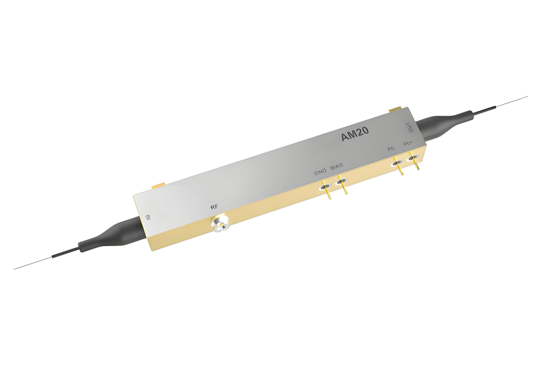
C-Band 20/40 GHz Extended Temperature Intensity Modulator
WXG Broadband Analog Intensity Modulators combine high linearity with low driving voltage and small footprint, covering frequency range from 20 GHz to beyond 40 GHz (AM20-XT: 20 - 30 GHz; AM40-XT: > 30 GHz). The experience and know-how of WXG engineers is available to customize our products to the customer’s specificrequirements.
Model: GKAM20|40
Applications:
RF over Fiber (ROF)
Wavelength:nm
Contact: Dongz
Email: Sales@wxgphotonics.com
Dongz
Email: Sales@wxgphotonics.com
Dongz
Email: Sales@wxgphotonics.com
Features
- Titanium Indiffused Waveguides
- X-Cut LiNbO3
- Operating at C+L-Band
- Electro-Optic Bandwidth > 32 GHz
- Low Drive Voltage Compatible with Commercially Available Drivers
- Low Optical Insertion Loss
- Integrated Photodiode
- Integrated Polarizer
- Hermatically Sealed
- Operating and Storage Temperature at - 55 to + 85°C
Applications
- Digital/Analog Transmission
- High Frequency RF over Fiber Optic Links
- Delay Lines Systems
- Instrumentation
Optical and Electrical Specifications
| Parameter | Conditions | Value (AM20-XT) | Value (AM40-XT) | Unit |
|---|---|---|---|---|
| Optical | ||||
| Operating Wavelength | - | 1525 - 1615 | 1525 - 1615 | nm |
| Insertion Loss | No connectorsWith connectors | < 4.5 (3.5 typ) < 5.0 (4.0 typ) | < 5.0 (4.0 typ) < 5.5 (4.5 typ) | dB |
| Optical Return Loss | No connectors | > 45 | > 45 | dB |
| Polarization Extinction Ratio | - | > 20 (23 typ) | > 20 (23 typ) | dB |
Electrical – RF Port
| S21 Electro-Optic Bandwidth | - 3 dBe | > 20 (23 typ) | > 30 (31 typ) | GHz |
|---|---|---|---|---|
| S11 Electrical Return Loss | 40 MHz – 20 GHz | < - 10 (- 12 typ) | < - 10 (- 12 typ) | dB |
| 20 GHz – 35 GHz | - | < - 8 (- 10 typ) | - | |
| RF Vπ Voltage | @ 1 kHz | < 5.0 (4.5 typ) | < 5.2 (4.7 typ) | V |
| @ 20 GHz | 6.0 | 6.0 | V | |
| RF Impedance | - | 50 | 50 | Ω |
| Bias Vπ Voltage | @ 1 kHz | < 5.5 (5.0 typ) | < 5.5 (5.0 typ) | V |
| Bias Impedance | @ DC | 1 | 1 | MΩ |
| Photodiode Responsivity | - | > 1 x 10⁻³ | > 1 x 10⁻³ | mA/W |
| Linearity | - | ± 10% | ± 10% | - |
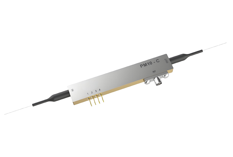
Pinout and Fiber Specifications
| RF Connector | V-Connector |
|---|---|
| Bias and PD Connector | LEAD pins |
| Input Fiber | Corning/Fujikura SM15P UV/UV250 (Panda Fiber), > 1.3 m, 900 µm loose tube fiber |
| Output Fiber | Corning/Fujikura SM15P UV/UV250 (Panda Fiber), > 1.3 m, 900 µm loose tube fiber |
Absolute Maximum Ratings
| Parameter | Conditions | Min | Max | Unit |
|---|---|---|---|---|
| Maximum RF Input Power | RF port AC coupled | - | 25 | dBm |
| Maximum Optical Input Power | CW | - | 100 | mW |
| Operating Case Temperature | AM20-XT/AM40-XT | - 55 | + 85 | °C |
| Storage Temperature | AM20-XT/AM40-XT | - 55 | + 85 | °C |
| Maximum OperatingTemperature Variation Rate | AM20-XT/AM40-XT | - | 10 | °C/min |
| Operating Humidity | - | 5 | 85 | % |
| Leads Soldering Temperature | - | - | + 250 | °C |
| Leads Soldering Time | - | - | 10 | s |
Mechanical Outline
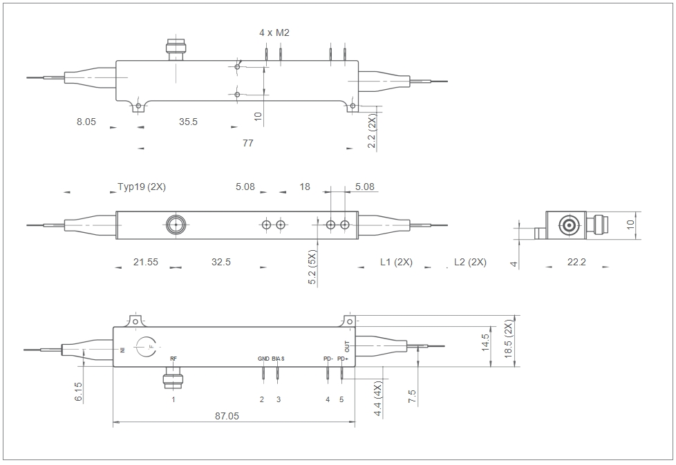
AM20-XT and AM40-XT have same footprints. All dimensions measured in mm. L1 is fiber length with 900 µm loose tube. L2 is length of bare fiber.
Pinout Information
| Pin | Name | Description |
|---|---|---|
| 1 | RF | input,V-connector |
| 2 | GND | Ground |
| 3 | Bias | Bias Voltage |
| 4 | PD-C | Photodiode cathode |
| 5 | PD-A | Photodiode anode |
Ordering Information
103076200001
AM20-XT, C-Band 20 GHz Extended Temperature Intensity Modulator(> 1.3 m, 900 μm PMF/PMF loose tube fiber)
103076200004
AM40-XT, C-Band 40 GHz Extended Temperature Intensity Modulator(> 1.3 m, 900 μm PMF/PMF loose tube fiber)
Product Inquiry
Leading manufacturer of photodetector modules and fiber optic sensing system modules